Executive summary of Hongqiao Airport Apron Resonance Free Vibratory Piling Monitoring Test
This executive summary presents the method statement and main analysis data for the feasibility study of Hongqiao Airport Apron Resonance Free Vibratory Piling project.
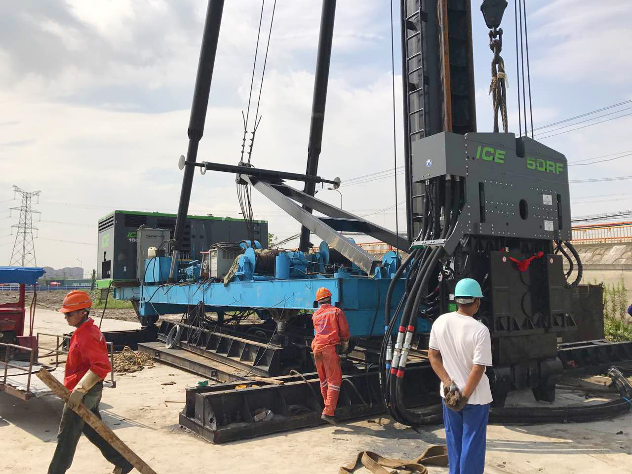
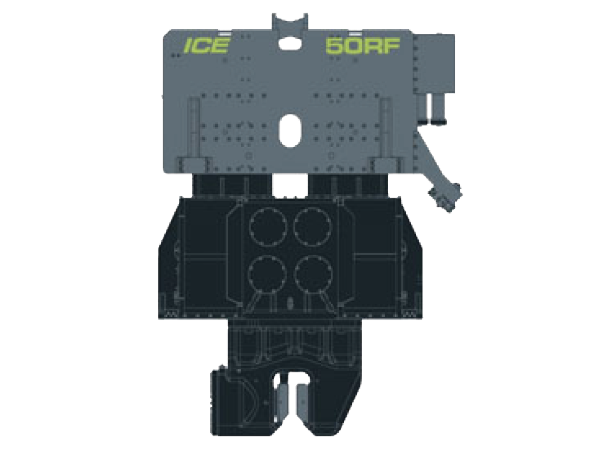
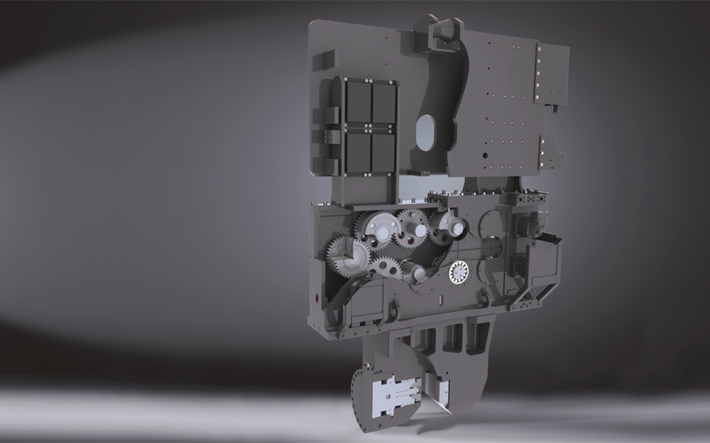
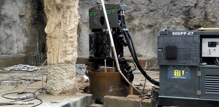
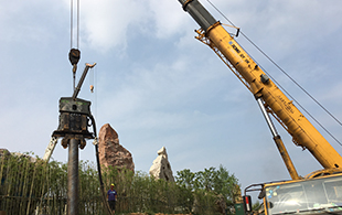
Hongqiao Airport’s apron is affected by ground settlement, the proposed method to remedy the settlement issue is driving steel casings into the soil by resonance free vibratory hammer. To assess the possible effect of resonance free vibratory piling hammers on metro line 2, which runs close to the site, a test site was selected on Shanghai’s Yanjiang Corridor project for comprehensive vibration and settlement testing. The test site’s soil conditions are representative for the Shanghai region and have universal applicability in the city. The test piles chosen were 60m long steel casings with a diameter of 700mm. Results were collected during the installation of the first and second 15m section of the pile. The pile driving equipment used for the test was an ICE 50RF resonance free vibratory hammer.
The following measurement standards were followed during the test
1)中华人民共和国国家标准《工程测量规范》(GB50026-2007)
2)中华人民共和国国家标准《爆破安全规程》(GB6722-2014)
3)上海市工程建设规范《地基基础设计规范》(DGJ08-11-2010)
4)上海市工程建设规范《基坑工程技术规范》(DG/TJ08-61-2010)
5)上海市工程建设规范《基坑工程施工监测规程》(DG/TJ08-2001-2006)
6)上海市工程建设规范《静力触探技术规程》(DG/TJ08-2189-2015)
7)有关本项目的设计文件及委托方要求
To determine the effect of resonance free vibratory pile driving equipment on the surrounding environment, including effects of resonance and changes in soil characteristics.
The test measured two points adjacent to the foundation pile, one data collection point at 2.5m distance, and one at 5m distance from the casing. For each point measurements were done at different depths: 2.5m 5m 7.5m and 10m depth. Parameters to be measured were vibration levels, soil displacement, and pore water pressure.
1) lateral soil displacement (tilt measurement) monitoring data collected from 8 locations * 5 times
2) Soil subsidence monitoring data collected for 8 locations * 5 times
3) pore water pressure monitoring 8 locations * 5 times
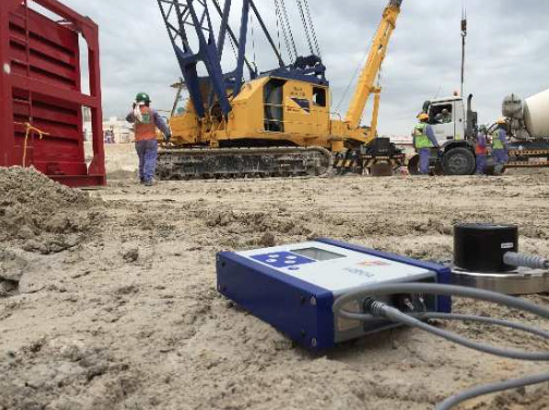
4) vibration monitoring 8 positions around the pile
Testing objective
The objective is to monitor the horizontal displacement of the inclinometer embedded in the soil, and monitor the horizontal displacement of the deep soil layers during the test pile driving.
Method
PVC inclinometer tubes were driven into the soil to a depth of 30m at 2.5m, 5m, 7.5m, and 10m distance of the casing. The PVC pipes have two internal groves that guide the inclinometer down the pipe; lateral soil movements will deform the PVC pipe and provide information about lateral soil movements that occur during pile driving.

Installation method
The PVC inclination pipe is bored into the soil
Lateral displacement results
For measurement point TX5 at 2.5 meter distance from the pile and 30m depth the maximum soil displacement was 3.77mm.

Testing objective
To monitor subsidence of magnetic spheres inserted in the soil at specified depth during pile driving.
Method
The project used the "magnetic ring method", sensors monitor the position of the magnetic rings before, during, and after driving. The position of 3 of the magnetic rings corresponded with the subway tunnel’s top, center, and bottom, all 3 meters distance a part. A further 4 rings were inserted at 5-meter intervals to collect information from deeper soil layers.

Measuring points buried "Magnetic ring method" soil stratification, settlement test uses the "drilling method" for the installation for the measurement of lateral soil movement at pre-determined depth intervals. The magnetic rings should be inserted one week prior to the test to ensure stable position in the soil.
u Result
At measurement point FC8 at 10m distance from the pile and 26 depth the maximum soil subsidence was 8.57mm.
Testing objective
Changes in pore pressure are an indication of soil disturbance.
Testing method
The pore water pressure sensor was set to the required depth by drilling method and three sensors were set up at different depths in each borehole.
The method of "drilling" (backfilling method) is used to install the measuring points.
The water pressure variation at the base of the monitoring station KY8 at 21-meter depth and a distance of 2.5 meters was the largest at 7.3 Kpa.
∫
Purpose of monitoring
To monitor the potential impact of the resonance free vibratory hammer on adjacent structures, such as buildings, metro tunnels, train tracks and predict tunnel structure fatigue or damage. The vibration characteristics of the pile clamped by the resonance free vibratory hammer is measured with a vibration monitor.
testing methodology
Vibration monitoring point is set up at 3m distance from the pile
test results
Monitoring point BP1 at 2.5 meters from the steel pipe test pile measured the highest maximum ground vibration value of 7.37mm/s.
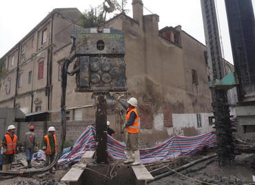
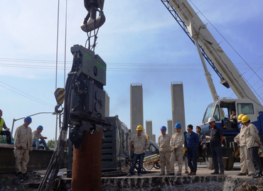
On August 22nd 2017 at 15.20 in the afternoon, the test pile installation commenced. Pile driving was completed around 18.00. In total two pile sections were driven. Each pile section was driven in 4 minutes, positioning and welding of the casing sections took about 2 hours. On August 24th at 7.20 in the morning the third and fourth section were added and driven to depth by vibratory hammer. The pile driving was completed around 11.00 AM. The third and fourth pile section were driven in 8 minutes each. This completed the pile driving monitoring test.
Measurement data summary
| Measurement value | Analysis point | Max deviation allowed by the Norms | Largest deviation | depth | position |
| lateral displacement | TX5 | 40mm | 3.77mm | 30m | 2.5m |
| Subsidence | FC8 | No greater than 20mm At Surface no more than 39mm | 8.57mm | 26m | 10m |
| Pore pressure | KY8 | 7.3Kpa | 21m | 2.5m | |
| Vibration analysis | BP1 | 100mm/s | 7.37mm/s | 0m | 2.5m |
The results of this test show no specific relationship between pile driving by resonance free vibratory piling hammer and changes in the soil profile, especially at a distance greater than 5 meters from the pile. We conclude that there is no measurable impact on the soil from the pile driving activity.


 Search terms: Product Name, Type, Application.


|
Rent Piling Equipment |
 |
Virtual Visit To Our Factory |
 |
Order Spare Parts |
 |